Liquid Rocketry Lab
Liquid Rocketry Lab (LRL) is a team of multidisplinary North Carolina State University students. We are a liquid propulsion and launch vehicle systems research team whose objective is to send a liquid fueled rocket past the Kármán line. The vast majority of my time has been spent on the engine team as lead and major design owner, although I began my time on the test stand plumbing team.
Engine Development Lead
I spent my remaining years in undergrad leading and closing out the development of Argenta 7A. The moment the fall 2025 semester began, I went deep into engine manufacturing. We had spend the last ~year developing the injector, catalyst bed, and thrust chamber and I set out to make this engine exist as soon as possible. There's a lot of old past tense yammering in here but you just want to see photos, so here you go.
Modifying the 4-jaw chuck to fit on the 4th axis. We also were using a extended face mill to machine the thrust chamber parts. The things you do when you don't have a lathe large enough...
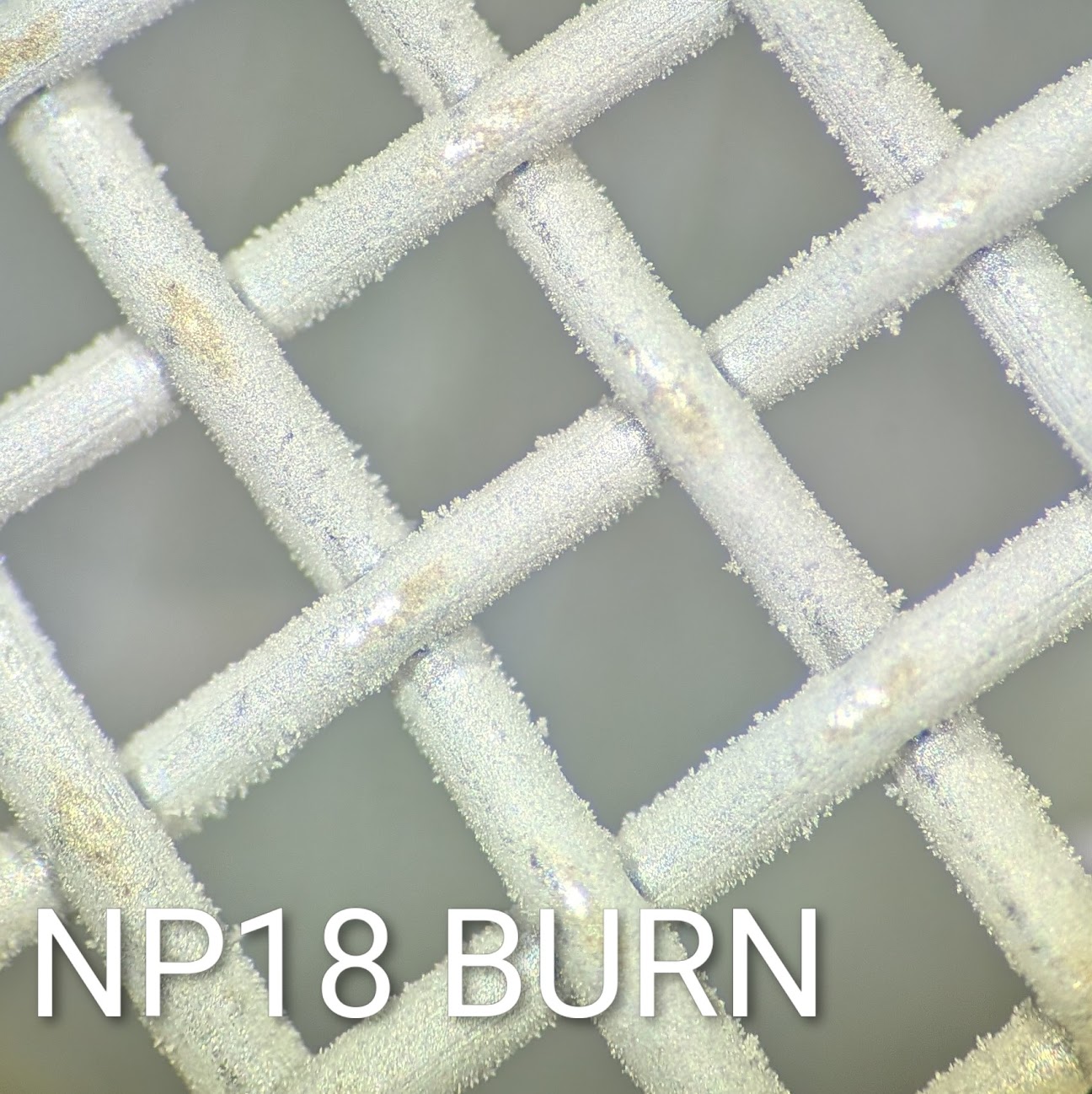
Switching gears, we had to electroplate stainless steel wire meshes with nickel then silver to create the catalyst bed meshes. We spent a solid month figuring out the procedures and equipment to perform full scale production, as we had only done subscale testing the semester prior. We created and iterated our own nickel striking solutions, innovated on our cooling method (an insane amount of LN2), and tackled the chemistry of the solutions to keep them stable and in spec.
The electroplating setup itself was a titanium sheet metal anode support with two 150A/5V power supplies flanking it. The anode bath either contained pure nickel or pure silver. After 13 days of straight production, killing one NCSU fumehood and one of our power supplies, we produced over 100 nickel plated stainless steel meshes that were ready for silver plating (the substantially easier/quicker process). The nickel solution was this wonderful mix of hydrochloric acid and nickel (II) hexahydrate. The silver bath was an even more wonderful solution of various soluable cyanides.
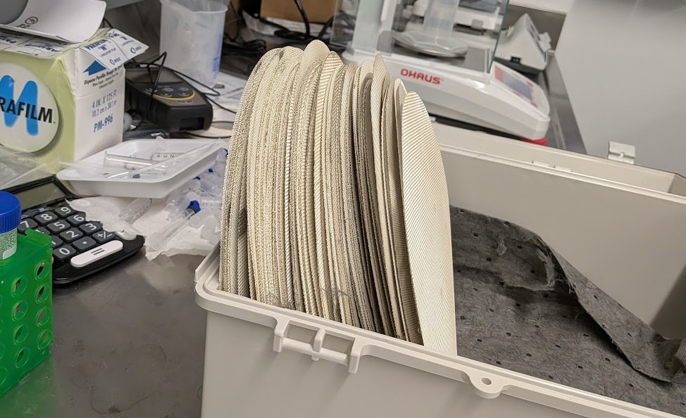
A bunch of silver meshes.
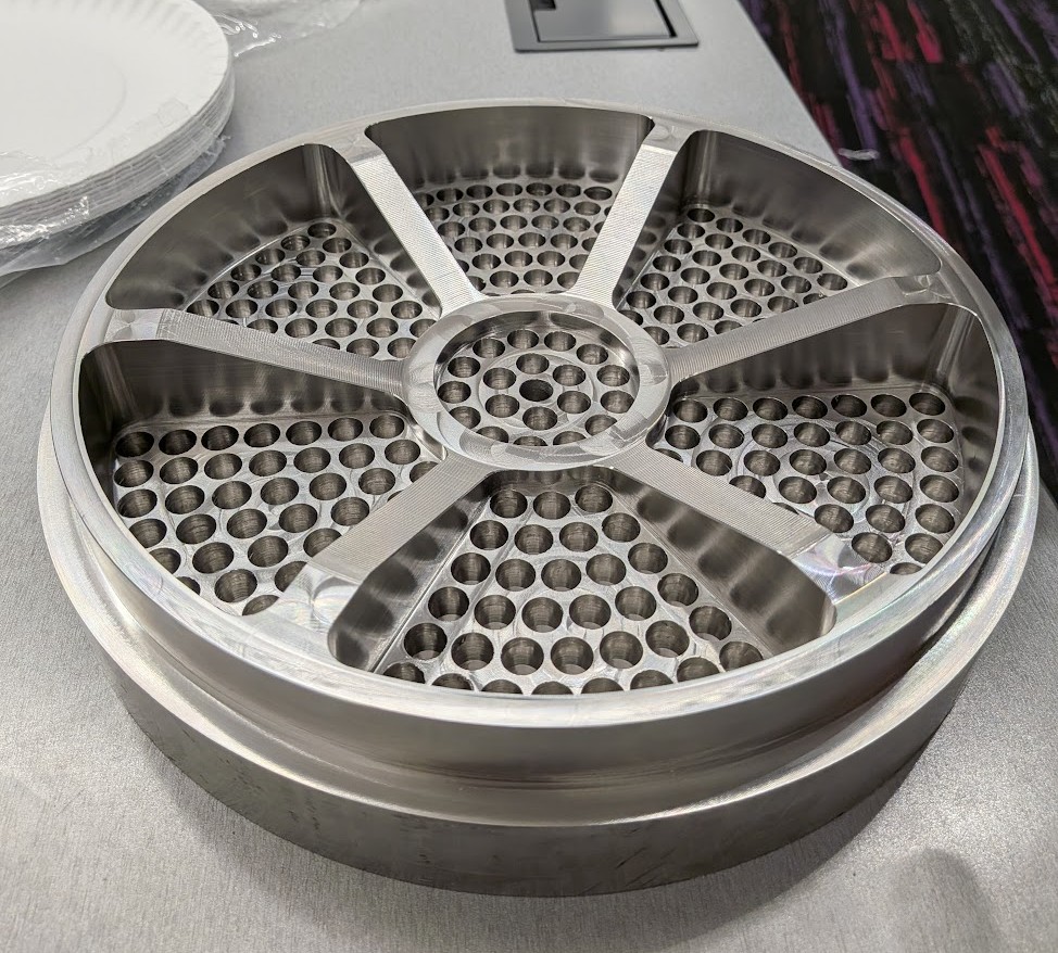
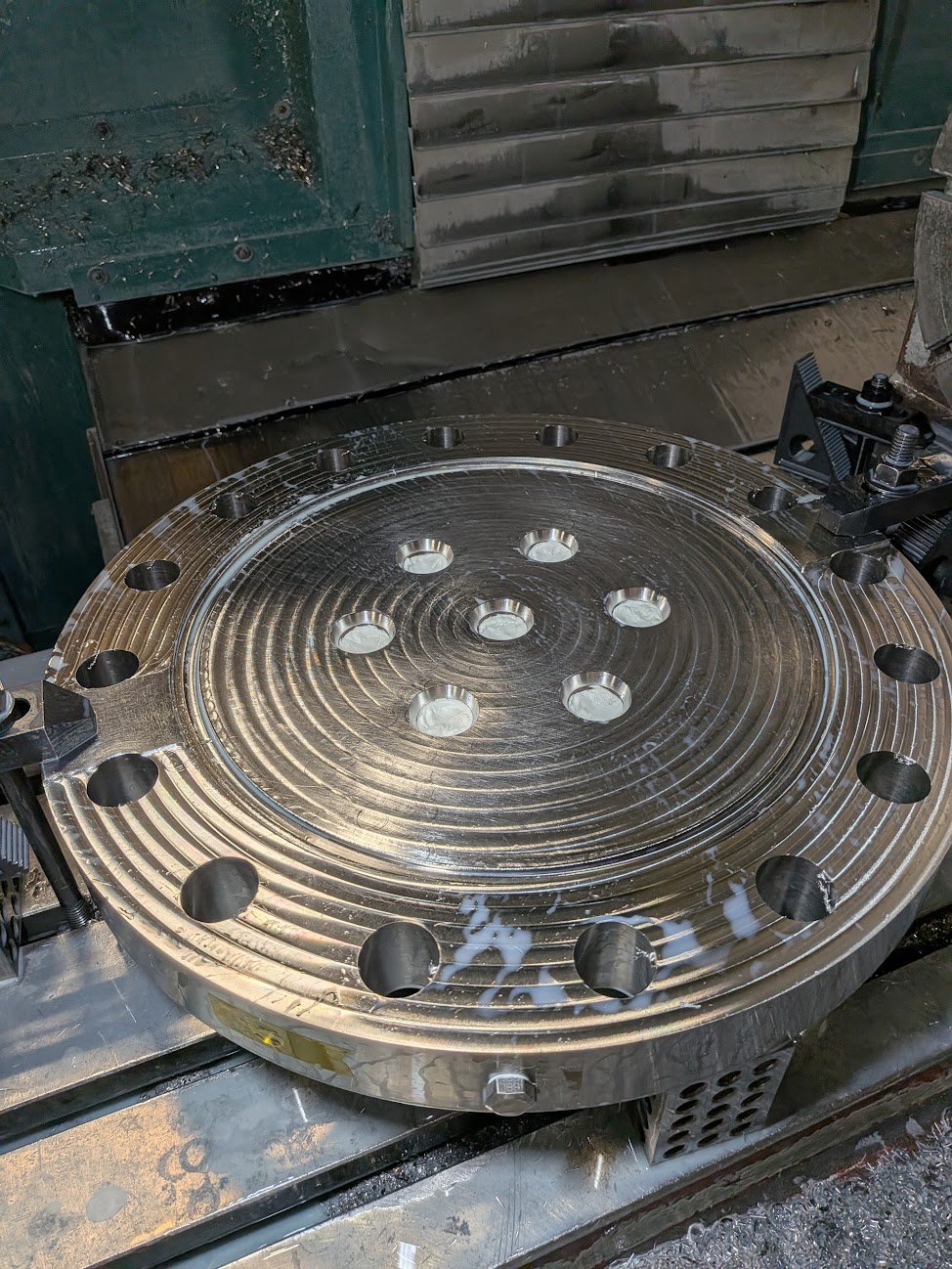
OP1 of the catalyst bed support plate finished. This part had a 9" tube welded on the other side where the silver meshes are compressed into. The decomposed HTP (oxygen + steam) flows through the 240 holes drilled in OP1.
Some finish machining on the welded injector assembly.
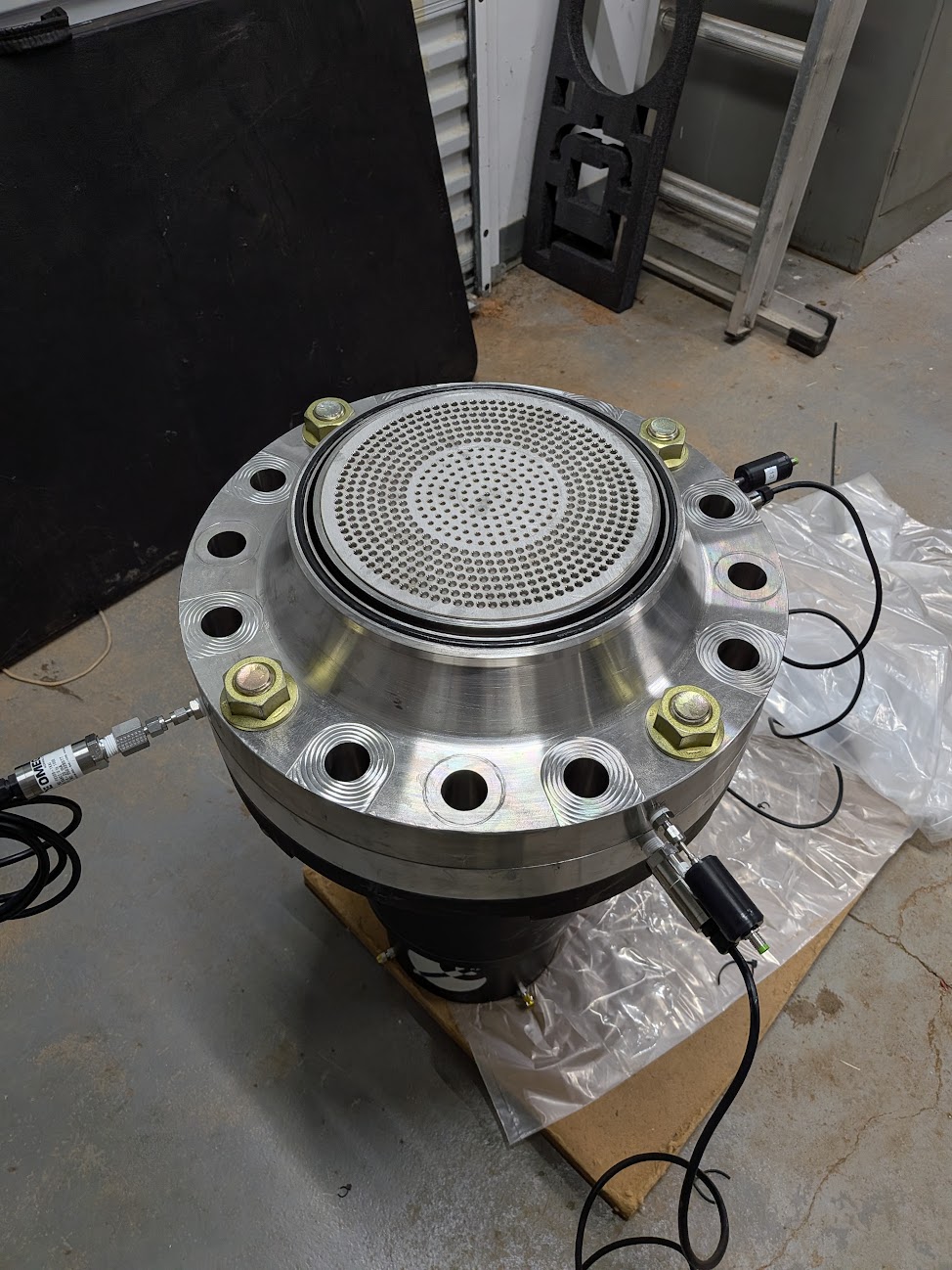
At the end of all that work, you get to compress the meshes until the pneumatic press is begging for mercy, then put all of those assemblies together into the engine. At this point, you may be expecting a diatribe of "integration hell". Luckily, I did my job measuring each assembly well enough to where it just fit together, surprisingly.
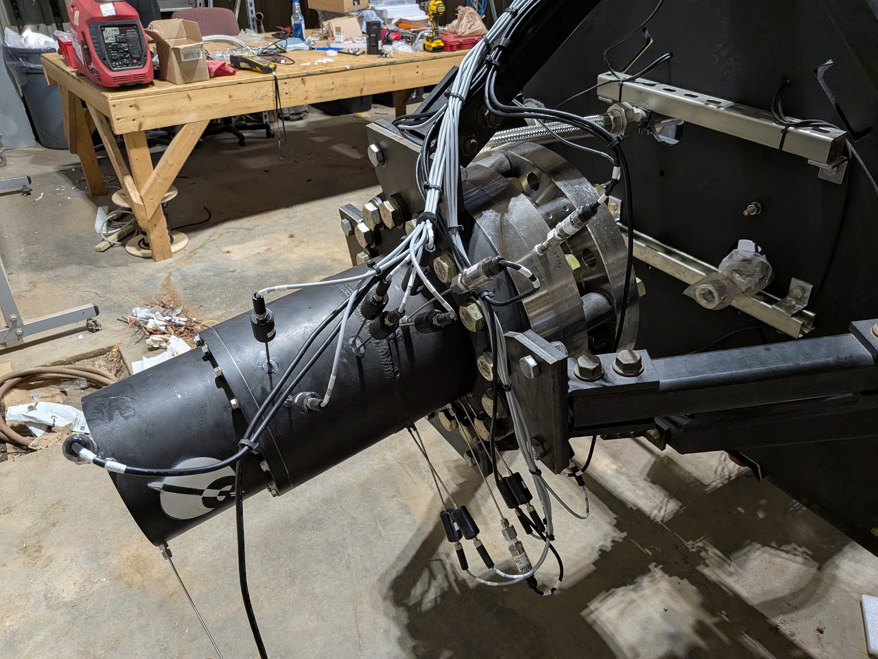
You put enough parts together and at some point it turns into an engine. I had designed and produced a throat insert that sealed the combustion chamber off and had a hydraulic QD that allowed us to purge the engine with dry N2 to keep the catalyst bed stack from deteriorating.
Past Tense Yammering
I have continued to learn since my time as an engine team member and have reverted some of my previous design choices due to my expanding knowledge base. I returned the injector to stainless steel from mild steel due to the fact that we would have to plate the steel injector with nickel, which would be a dubious process at best with the geometry of the fuel manifold and the small orifices. I was able to source the raw material extremely cheaply which enabled the team to utilize a stainless steel injector. Cost is amajordriving factor behind engineering decisions on the team. This final version of the injector only costs the team a few hundred dollars out of pocket, which was even cheaper than the previous mild steel version.
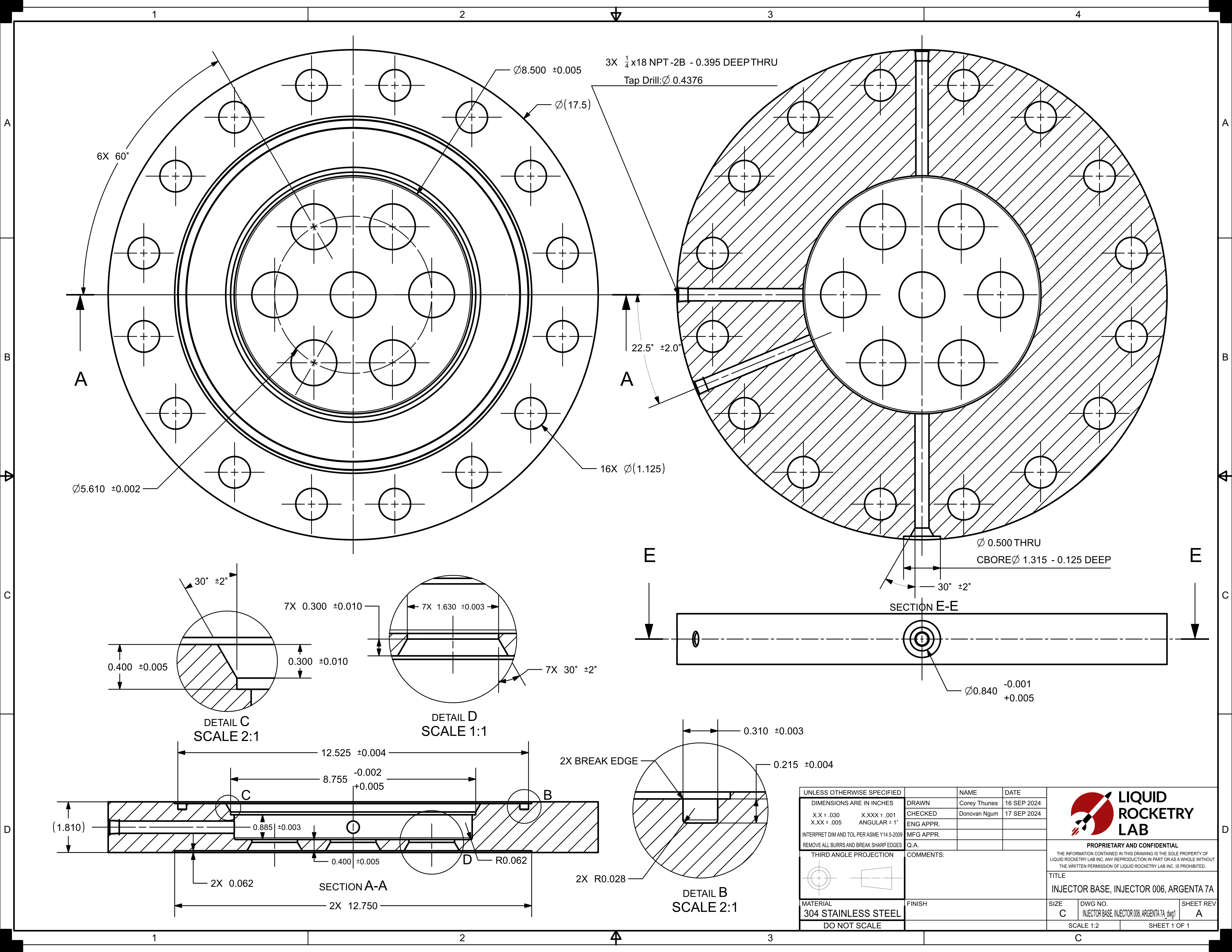
Each part of the injector was optimized and tailored to be made in-house. The assembly as a whole has quite loose tolerances and simple manufacturing processes which is very important when you're a broke college team. I made drawings for all of the manufactured components of the injector as well, but beware GD&T enthusiasts, don't look too closely, I'm still learning.
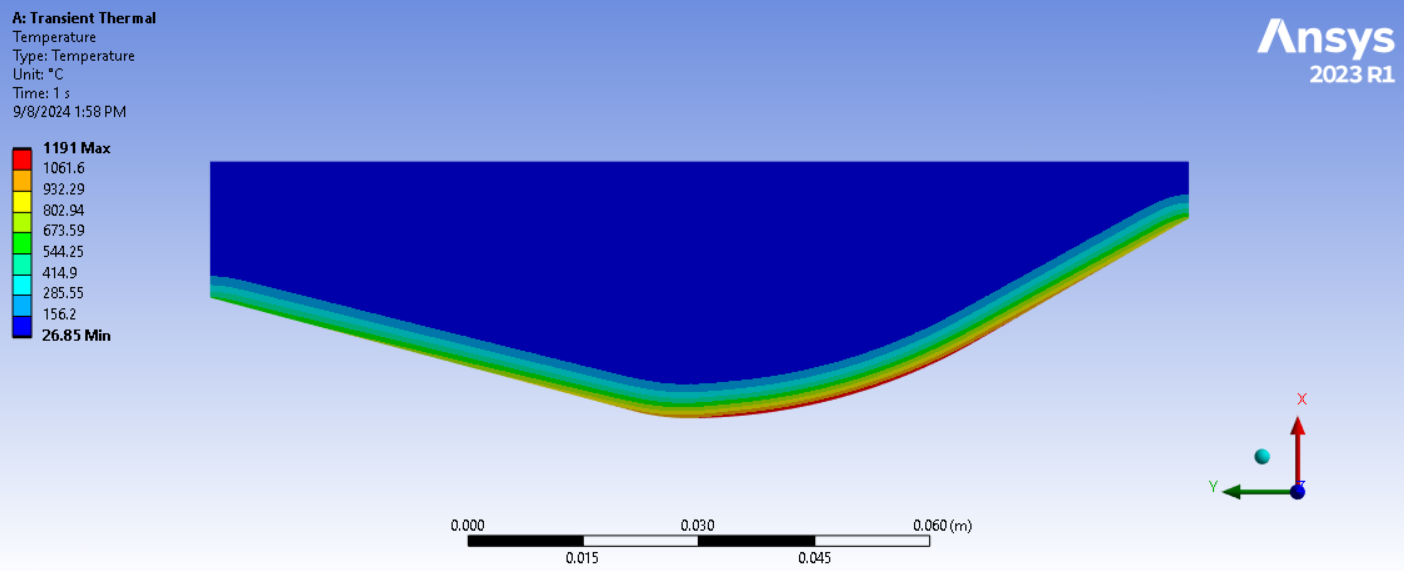
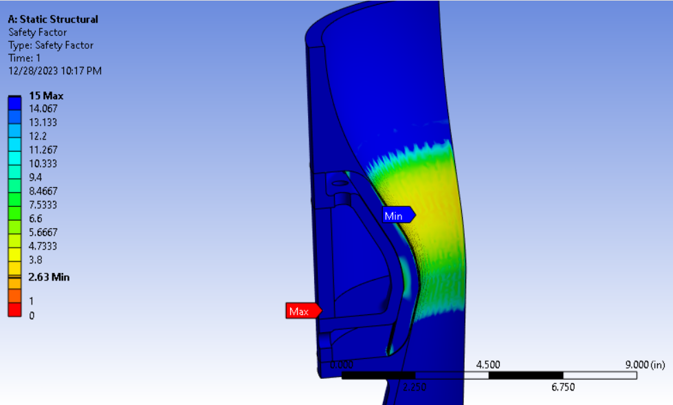
I led the initiative to change our decision of using an ablative throat insert in the nozzle to a stainless steel throat insert. Our previous analysis said a stainless steel throat would not survive even a 1 second hot fire, which led to using an ablative throat insert. This has always bugged me as the cost is prohibitive and has a long lead time. I decided to revisit this analysis and teach myself 2D transient thermal simulations in Ansys Mechanical and determine if we can actually use a stainless steel throat insert. Turns out, we can.
The previous analysis had used 316 stainless in Ansys, which doesn't have tabulated properties with respect to temperature. Switching the simulation material to 304, which does have these properties, showed us that the throat would not melt during a 1 second hot fire. There are some more simulations and analysis to perform to tie up the loose ends, but we've decided to move forward with this idea for the time being.
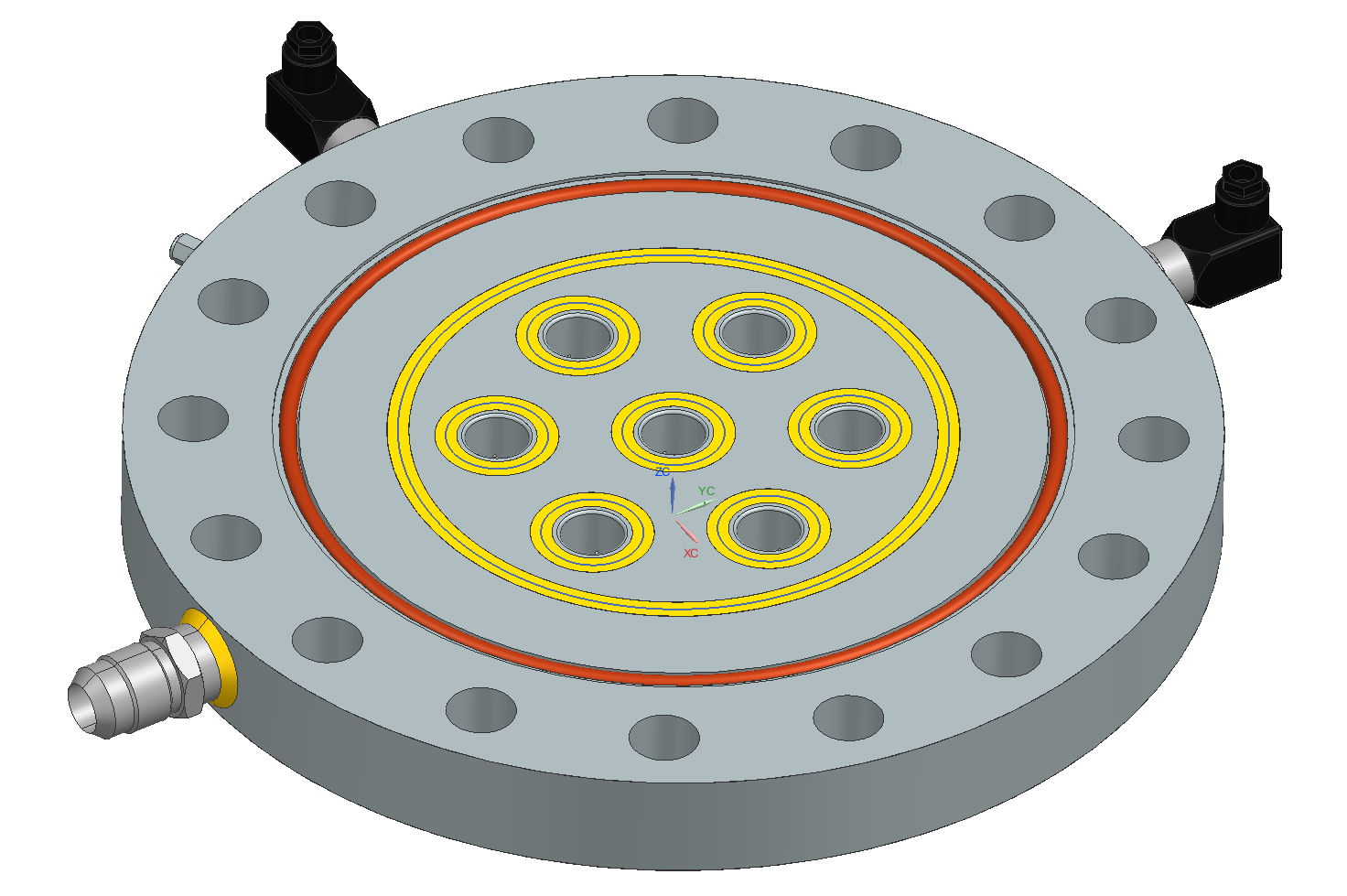
I led and was involved in a few other initatives, such as changing the team's fuel from RP-1 to Jet A for logistical and cost reasons, using Viton O-rings for the first engine instead of metal seals, designing the startup procedure for the engine and performing preliminary coupled transient thermal-structural simulations of the thrust chamber.
We still have a lot of work to do before we hot fire, but I plan to lead my team to a successful and ON SCHEDULE completion of our goals.
Engine Team
After my first year, I was moved onto the engine team where I found my role as a design and manufacturing engineer for our first engine. The engine team was just starting and none of us really knew what to do or where to begin. All we knew is that the engine had to run on high test peroxide (HTP) and RP-1 (now Jet A) and had to produce 7,000 lbf of thrust.
We certainly struggled as there were only a few of us and we hada lotto learn before we could really be confident in any one design. This issue manifested itself several times during design cycles; we would learn enough to start a design, get deep into it, learn more and realize our design wouldn't work. This situation occured twice before we we were able to confidently settle into a design, but not without more minor design setbacks that required even more learning.
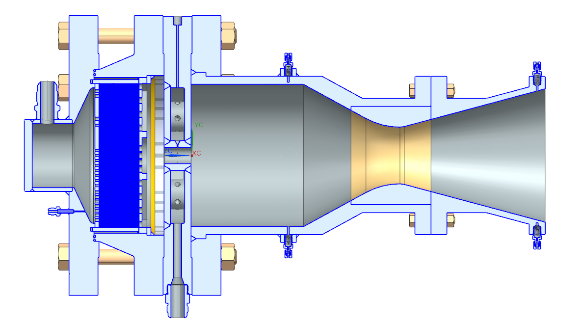
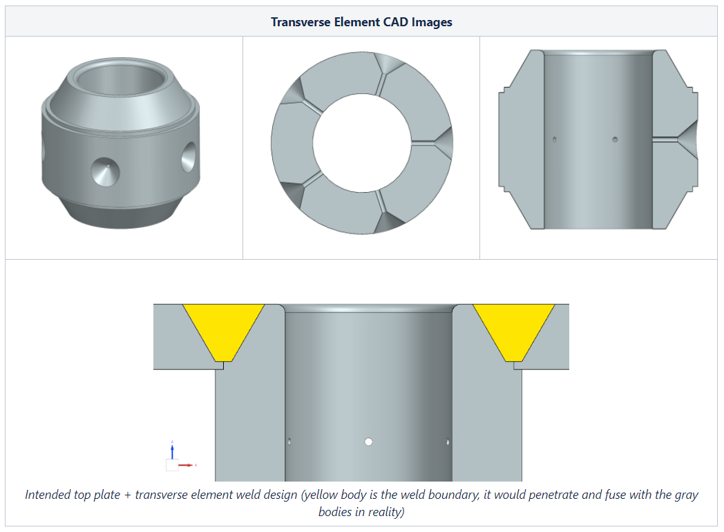
The highest rate of iteration was during the Spring 2024 semester, where we were learning at such an insane rate we changed the design seemingly everyday. Eventually, the iteration slowed and we settled into a engine that ran on 90% HTP and RP-1, utilized a seven element transverse type injector, a full flow silver catalyst bed, and a heatsink chamber. My personal responsibility was to essentially take the mathematical and simulation modeling of the injector and thrust chamber and turn them intomanufacturable and cheapcomponents.
I vastly expanded my knowledge in design for manufacturing, thermal structural analysis, welding standards, part deletion, material science, and compressible flows. One major design change that I pioneered was changing the injector and thrust chamber material from a stainless steel grade to a carbon steel grade, A105 on the injector and 1018 on the thrust chamber. This decision was mostly prompted by the price of the stainless steel relative to a carbon steel. We completed the analysis and came to the conclusion that grades of carbon steel could survive a hot fire duration of 3 seconds without structural failure. This decision saved the team several thousand dollars in manufacturing costs.
Additionally, as a quick project to assist with the members working on the throat cooling trade study, I designed a water cooled throat that would use our team's firetruck as a water supply. I performed structural and thermal analyses with the assistance of the modeling focused members.
Test Stand Plumbing Team
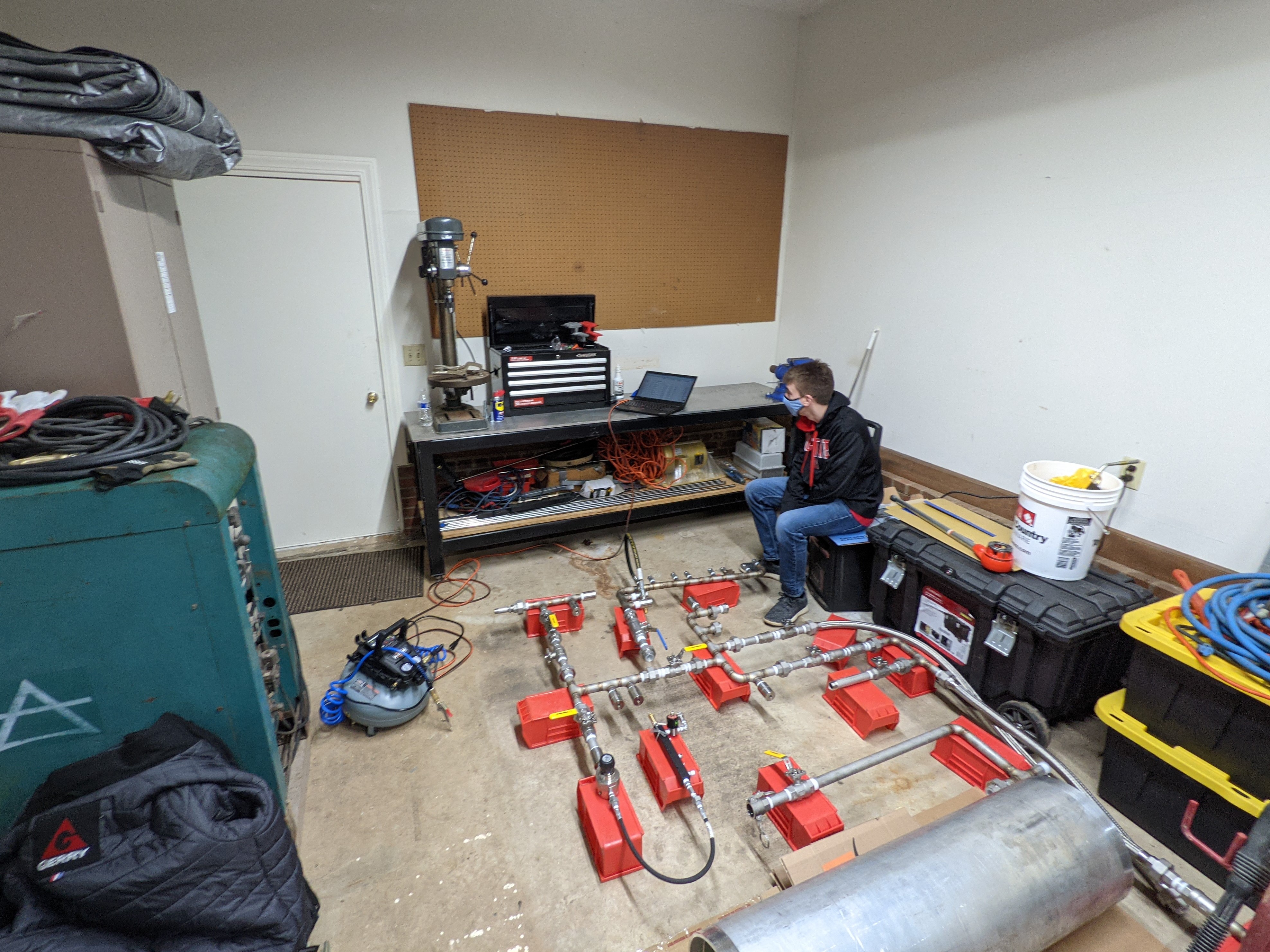
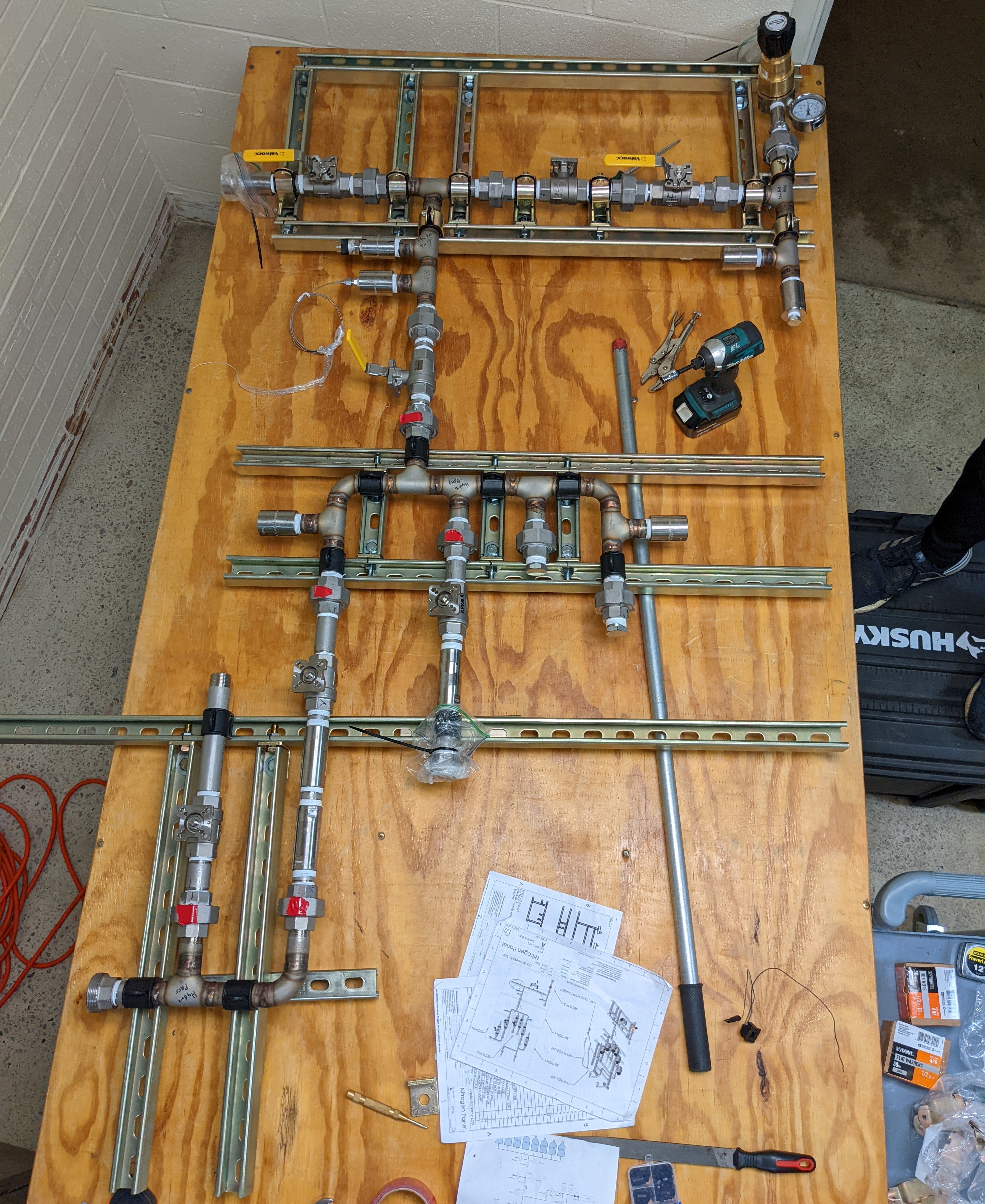
In my first year of college, I was a member of the plumbing team. The plumbing team designs and builds the systems that deliver pressurized gas and propellants to where they're needed.
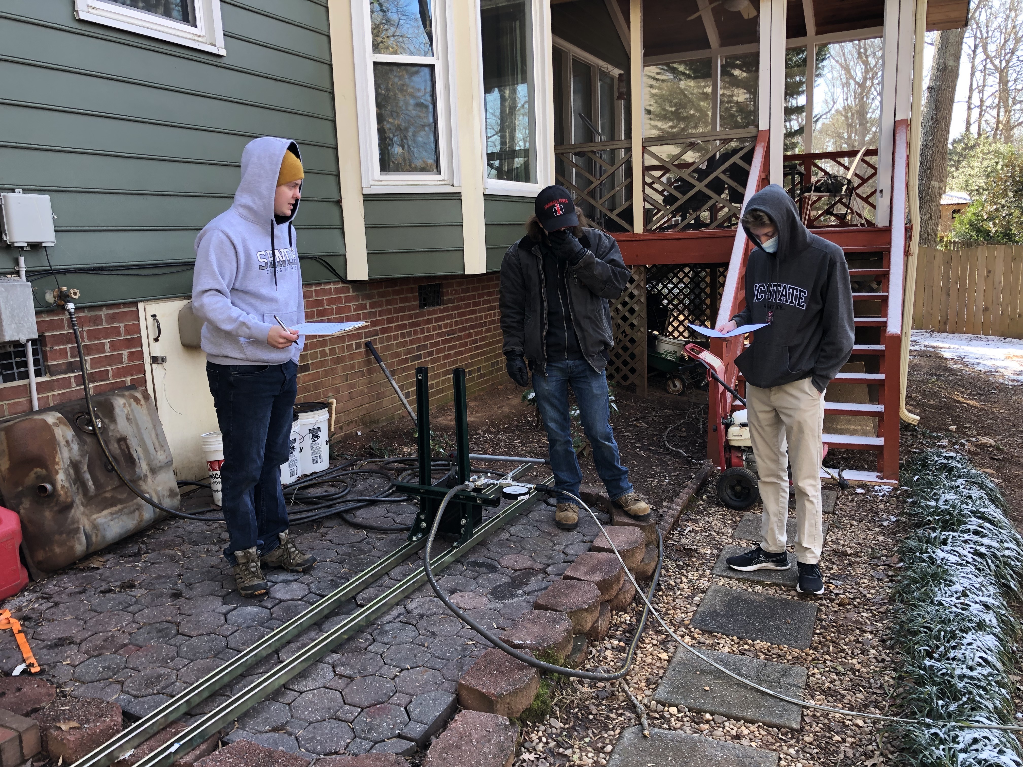
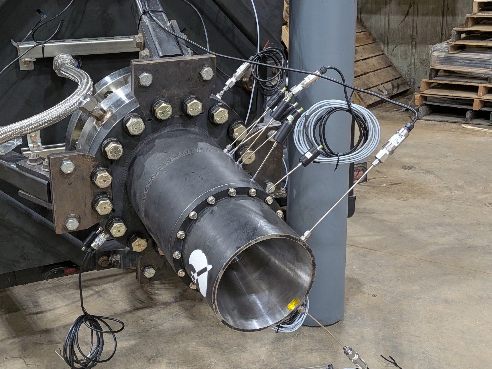
Most of my time was spent assembling plumbing sections and hydrostatically testing them to 1500-3000 psi. We maintained documentation of these tests within Jira.
After completion of the hydrostatic tests of the RP-1 plumbing, we installed all of the plumbing sections onto the test stand.
Near the end of my term as a plumbing engineer, the team successfully completed the first ever cold flow of the test stand. This involved pressurizing the RP-1 (now Jet A) side of the test stand to 1000 psi and venting water to the atmosphere. During this test, I took it upon myself to be responsible for general imagery and video of the event. My imagery and video is now widely used on social media, in professional settings, and internally. Some of the photos from the event can be seen on the photography page of this website.